
ROM Setup
The first thing to deal with was the ROM files for Space Invaders. I first combined all the 2kB chunks of the rom into one 8kB file. I then wrote a small script (romgen.c) to take this ROM file and convert it to a header file. I honestly just recommend loading by file. I did it this way since the micro-controller i was using does not have a file-system by default and I am only using this to emulate space invaders and not any other games.
Memory Setup
With the ROM in place, I moved on to setting up the memory structure. For this, I simply allocated 16kB of ram and inserted the ROM into the first 8 kB of it. I set a few constants declaring where in the memory things like the stack and program start. Most of my constants are derived from this link which has an excellent explanation of how memory is utilized in space invaders.
#define MEMORY_SIZE 0x4000
#define ROM_SIZE 0x2000
#define STACK_START 0x2400
#define PROGRAM_START 0x0000
Here is a graphical representation of the memory model for space invaders:
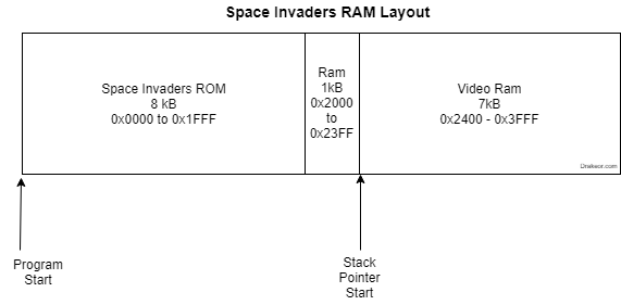
There are a few things to note here:
- ROM is typically write-protected, so for anything that stores/loads to memory, we need to check to see if it is attempting to write to the ROM portion. It's worth noting that some implementations ignore this altogether in favor of performance, or because the program will actually modify it's own code (Though I personally have not seen any 8080 code in or outside of Space Invaders that attempts this yet.. I may be wrong).
- Each byte in the video ram corresponds to a pixel on the screen. (The screen resolution of Space Invaders is 224x256).
CPU Setup
According to the Intel 8080 Programmer's Manual, the Intel 8080 has an 8-bit accumulator register, six 8-bit general purpose registers (Labeled B, C, D, E, H, L), one 16-bit stack pointer, and one 16-bit program counter. The general purpose registers can be addressed as 16-bit register pairs (Labeled BC, DE, and HL) and the last register is an 8-bit conditional code register (or program status word register). For ease of visibility, I've put together a simple diagram to outline the 8080 registers.
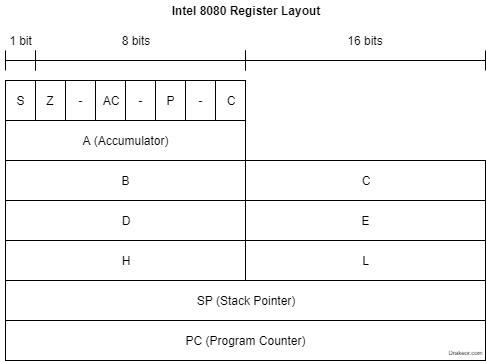
I've defined the structure for the CPU following this diagram. For the 16-bit register pairs as well as the PSW, I'm using unions to keep it simple. Note that the reversed order of the two registers in each register pair is intentional due to the endian-ness.
// Holds the current state of the CPU
struct cpustate {

    // A is the primary 8-bit accumulator
    uint8_t A;

    // 3 16-bit registers (BC, DE, HL)
    // that can function as 6 8-bit registers (B, C, D, E, H, L)
    union {
        struct {
            uint8_t C;
            uint8_t B;
        };
        uint16_t BC;
    };
    union {
        struct {
            uint8_t E;
            uint8_t D;
        };
        uint16_t DE;
    };
    union {
        struct {
            uint8_t L;
            uint8_t H;
        };
        uint16_t HL;
    };

    // 16-bit stack pointer
    uint16_t SP;

    // 16-bit program counter
    uint16_t PC;

    // 8-bit Flag register
    union {
        struct {
            uint8_t C:1;  // Carry, set if the last addition operation resulted in a carry
                                // or last sub required borrow
            uint8_t :1;
            uint8_t P:1;  // Parity bit, set if the number of true bits in the result is even
            uint8_t :1;
            uint8_t AC:1; // Auxiliary carry bit for binary coded decimal arithmetic
            uint8_t :1;
            uint8_t Z:1;  // Zero bit, set if the result is zero
            uint8_t S:1;  // Sign bit, set if the result is negative
        } FLAGS;
        uint8_t PSW;
    };
};
Next Steps
The next few steps will be implementing the first few opcodes and attempting to parse through the first few instructions of our 8080 emulator!